|
|

|
| Chapter
6: Motive Power (New) |
| |
| In this chapter I will endeavour to describe some of the steps in acquiring suitable new motive power for Grindham Shed. There is an existing fleet of P4 locomotives, as described elsewhere on this site, but this will need augmenting to provide sufficient motive power for a shed the size of that projected for Grindham. Here we will examine the stages of building locomotives from kits - for me the main attraction of the hobby. |
| |
| Introduction |
| |
| The range of ready to run models today is amazing and their quality truly stunning; 30 years ago this was far from the case! The range was limited and, with few exceptions, the quality was pretty mediocre. To get anything accurate and a bit different from the few models available meant that modellers had to build from kits or from scratch. Building kits introduced me to the pleasure that can result from constructing locomotives and the desire for greater accuracy led me eventually to P4. This, of course, rules out ready to run as a means to acquire motive power, but does leave open the option of conversion, which is described in the relevent chapter. Because of the finer wheel profiles and tolerances in the track, fitting some sort of compensation or springing is recommended for P4. The idea is to ensure that all wheels remain in contact with the rails at all times; this not only reduces the risk of derailment but, by improving the electrical pick-up, should enhance the running quality of the locomotive. The benefits of compensation apply to all scales and gauges and, although it naturally entails a bit more work, I maintain that building a reliable chassis is far easier using some form of compensation as opposed to a rigid one, especially as the number of axles increases. Compensation can be of three main types: Beam compensation, continuous springy beams, and individually sprung axles. I hope that the principles will become clear as this story unfolds. |
|
| Which loco? |
| |
| I decided on a GW 42XX 2-8-0T as an illustration of building a locomotive - the question is "Which one?". Steam locomotives were notorious for detail differences between members of the same class - even the highly standardised regime at Swindon allowed for many variations. The most visible difference between members of this class were those with the raised running plate over the cylinders (as this model) and those with a straight running plate. In addition, there were two distinctive patterns of boiler support fitted - large and small, and also two sizes of safety valve bonnet - tall or short. It is, therefore, essential to have a good photograph of the prototype you intend to model. Fortunately, my "Loco Finder", also available on this web site is an invaluable tool for this purpose which you can try for yourself. As a result of my research, I decided that this model will be 5236, fitted with large boiler support and short safety valve bonnet. As they were, without exception, painted black in BR days, the only other major issue is the style of crest on the tank side - clearly shown in my photograph to be the later BR one. The caption in the book says the photograph was taken in 1955, whereas I thought the later crest appeared in 1956 - an interesting anomaly! Still, the year is not material for my purpose, but importantly the photograph shows the locomotive to be in "ex-works" condition, though it is unlikely 5236 would have remained so for very long! Because the GW brass number plate survived Nationalisation, finding an etched plate with the required number used to be a further constraint. Happily, for many years now, a d-i-y number plate set has been available from Martin Finney, so - for unnamed locomotives at least - this is no longer a problem as will be demonstrated later in this saga. |
|
| Building a 42XX 2-8-0T |
| |
 The kit is from P.D.K Models and is etched bass and nickel silver, with some cast white metal components.
The photograph shows a fairly early stage. All the parts required for the basic structure had been detached from the fret, had their edges smoothed with a file, and surfaces cleaned with a fibre glass brush to remove any residue from the etching process. Cleanliness is vital for successful soldering Some further etched components can been seen awaiting their turn; the cab roof, which has been rolled to shape, is also visible. |
|
| Body - 2 |
| |
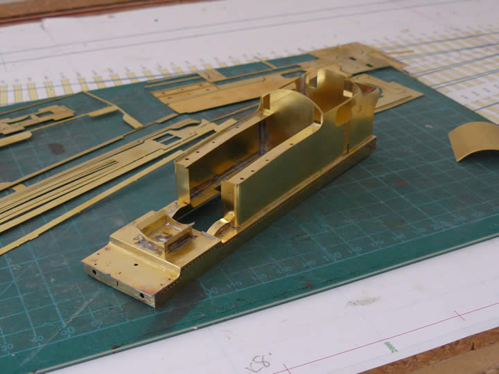
 Before assembly, the side tanks, footplate, splasher tops and the bunker rear were bent to shape; the curves were made using a drill of the appropriate diameter as a former. A dry run was then performed to ensure that all the parts fitted together correctly. So far, everything in this kit fits perfectly, and it is very well thought out.
Once satisfied that all was well, construction proper commenced, starting with the footplate. I always tack solder the components initially, then check for fit and squareness before running a seam of solder along the joint. The bolt visible in the smokebox saddle has been soldered in place to form the fixing for the chassis; there is another one at the rear. It is a very satisfying feeling seeing the model take shape. The model was thoroughly cleaned, rinsed and dried at the end of the session. |
|
| Body - 3 |
| |
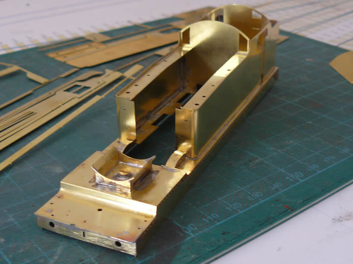
 Although, as yet, devoid of any detail, the characteristic shape of a large Great Western tank loco is already apparent.
The "skirt" under the running plate is a very neat idea to ensure that the running plate is square during construction. If this gets distorted then the tanks and subsequently the boiler will not fit true and the whole locomotive will be misshapen. Not only would this look wrong, the resulting imbalance could well have an adverse impact on the running characterstics. The "skirt" will be removed once the boiler and smokebox have been fitted, leaving just the valence; the etched join can be seen in the photograph. The frames do not sit flat in this view because the bolt, for fixing to the chassis, protrudes slightly below the bottom of the "skirt" at the rear of the body. |
|
| Body - 4 |
| |
 The basic shell in the previous pictures has been much improved by the addition of the overlays as seen here. The overlays have all the lovely rivet detail on them and this really transforms the model from the previous shots of the unadorned shell. Etched brass is a wonderful medium; to replicate this by punching out the rivets would be exceedingly difficult, very tedious and would not give such quality results.
She still looks rather odd with the "skirt" around the valence, and there is much detail to be added, but the model is really beginning to take shape. |
|
| Body - 5 |
| |
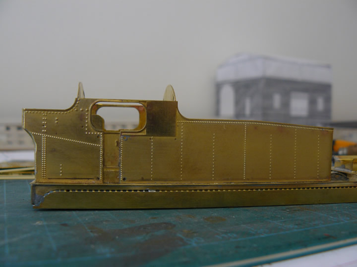
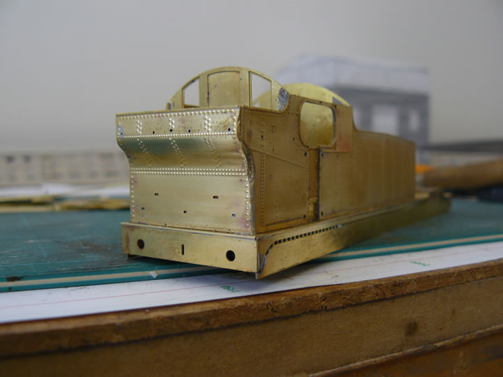 One of the trickiest jobs is forming the rear bunker - this not only curves as seen in the photograph, but the corners have to be rounded off as well. This latter process is only partially completed in the photograph. The basic rounding has been done with a fairly aggressive file; further work with a smooth file and "wet & dry" will be required to finish the job - but being very careful to avoid damaging the rivet detail!
There are still many details to be added, including the detailed overlay on the buffer beam, lamp irons and hand rails. The holes are to locate steps, etc. at a later stage. |
|
| Body - 6 |
| |
 For this shot I temporarily placed the smokebox, boiler and firebox roughly in position; now she is beginning to look the part! The close up shows the rivet detail on the tank sides more clearly; there is a further strip of rivets to be soldered along the bottom of the tank, and also round the bunker at the rear of the loco.
The curve at the front of the tanks was formed around the shank of a 2mm diameter drill; getting the bend in exactly the right place required a bit of care and the fit was checked before tack soldering the overlay in position. A further check for fit was then made, before soldering all the way round. The close up shows that the castings require some cleaning up to remove the slight mould line - though they were very crisp and clean; the inclusion of whitemetal castings not only obviates the need for some seriously tricky fabrication, but also adds some welcome weight, though I will stuff the smokebox, tanks and bunker with lead to assist with adhesion before the model is completed.I have also rolled the cab roof to the correct profile, and placed it roughly in position; it will have details added once it is fixed. The problem is painting the interior - best done before the roof is fitted; I will look at making it removable. I must now move on to the frames as I need to ensure that the boiler support lines up with the motion bracket before proceeding further with the body. |
|
| Frames - 1 |
| |
 Here are some of the main components of the chassis - the frames, coupling and connecting rods and the cylinders. The frames, as supplied, are of fold up construction. They feature enlarged apertures for the axles which are supported by beams that pivot inside the frames to provide compensation. I am still in two minds whether to proceed as per the kit, or to separate the sides and construct the frames with conventional hornblocks. The rivet detail, which needed pressing out, was done before I folded the frames up.
As can be seen, the coupling rods are in three separate sections, with each section being a laminate of two etched nickel silver parts; these have been sweated together but have yet to be cleaned up to remove the cusp left by the etching process. When dressed with a file they will appear to be solid castings. I formed the connecting rods at the same time. I have also formed the cylinder block which will require soldering around the cylinder covers. These 2-8-0T locomotives have an horrendous wheelbase which may be evident from this photograph, and will certainly become more apparent as construction proceeds. |
|
| Skirts off! |
| |
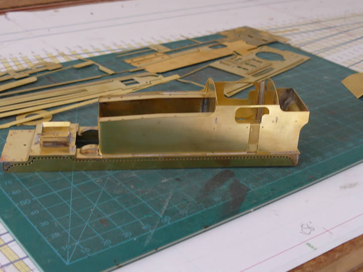
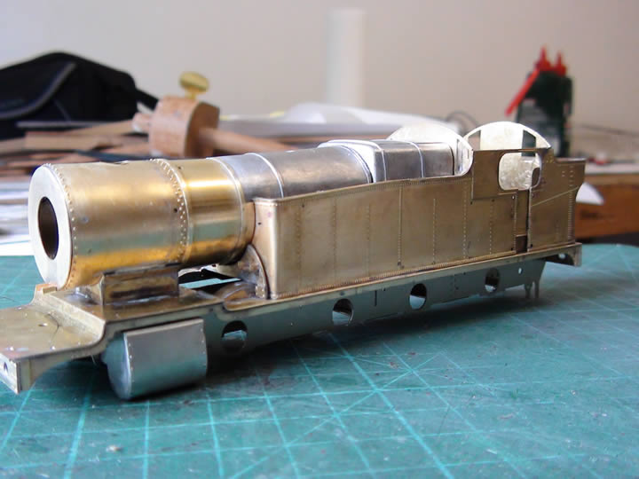 Having determined which boiler support would be required and with progress on the frames sufficient to determine its location with respect to the motion bracket, the support was soldered in position. This has enabled completion of the basic bodywork - the smoke box, boiler and firebox have now been soldered in position as can be seen from the photograph. The minimal "flash" on the castings has been cleaned off; the castings are really excellent quality.
With the boiler in place, the body is now sufficiently rigid to enable removal of the skirts; with the detail overlays added to the valence and buffer beams, the rivets along the base of the tanks and bunker, and with the front of the smoke box fitted, 5236 is really taking shape. Now the skirts have gone, it is possible to position the body on the frames with the cylinders in place, which will enable clearances to be checked for the wider placement of P4 wheels relative to the crosshead and slide bars. The body is substantially complete, apart from the small and delicate details; these will only be added once the chassis is built, to avoid potential damage in handling during that phase of the project. However, completion of the basic shell means that I can ensure that the motor and gearbox will fit as construction of the frames proceeds. |
|
| Gearbox - 1 |
| |
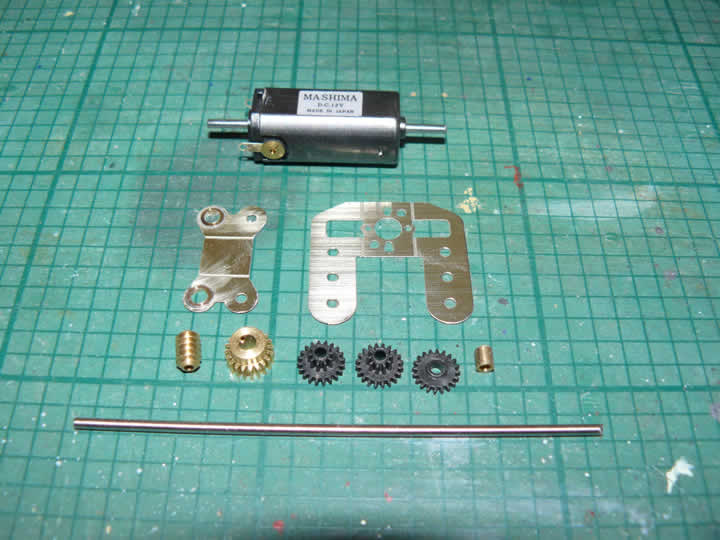 I have always favoured Portescap gearboxes. I know people criticise them for their noise, but I always found them very reliable and they gave good traction; being ready assembled, they required no effort to build and were, to my mind, good value despite their cost.
Sadly, they are no longer available but, happily, there are some very good alternative sources, one of which is the High Level range. The gearboxes are available in a variety of shapes, sizes and gear ratios - the example illustrated will build a 80:1 "LoadHauler+". It consists of a fold up frame and final drive carriage, and the worm and gear wheels to give the required reduction. The long shaft has to be cut into lengths to provide the shafts on which the gears rotate. In the photograph, the axle bushes have been soldered in place in the final drive carriage, and the relevant holes opened out to give a tight fit for the shafts. |
|
| Gearbox - 2 |
| |
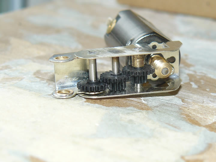 The assembled gearbox can be seen in the accompanying photograph. It may look complicated, but the instructions are detailed and comprehensive. The folds in the frames were strengthened with a seam of solder, the units then being thoroughly cleaned and dried before fitting the shafts and gears. Once assembled as shown, the shafts are fixed in the frames with a tiny drop of superglue, leaving the gears free to rotate on them.
This was my first attempt at building a HighLevel gearbox, and although it was a bit fiddly, it was not difficult and the end result seems to run very nicely. I chose this model as it accommodates a nice big and powerful motor - a range of different motors is also available from HighLevel. The separate final drive carriage gives some flexibility in placing the unit, depending on the amount of space available inside the body - happily the 2-8-0T is quite commodious. The brass final gear and the driven axle will be fitted in this carriage when mounting the gearbox in the loco. Visit the High Level website for their range of motors and gearboxes, where you can also download scale drawings to help select a suitable size, as well as find useful guidance on the gear ratio to choose. Usual disclaimers apply - this was my first purchase from HighLevel but, as can be seen, it all goes together very nicely and the mail order service was exemplary. |
|
| The Next Stage |
| |
| Now the gearbox has been assembled, I have no excuse for not proceeding with the frames! I am still agonising over whether to build as per the kit or to modify the frames and fit conventional hornblocks. This may take some time... |
|
|
|
 |
|