| Chapter
5: Structures & Scenery |
| |
| This chapter is concerned with the construction of the various structures - buildings, bridges and so on as well as the scenery. Most scenic work is done when the majority of the track and wiring is completed, to avoid collateral damage. However there are some things that have to be done even before track and wiring commence, such as construction of the incline for the coaling stage. Construction of structures can be undertaken in parallel, as they are built away from the layout and safe from damage. Details will be included as work progresses |
| |
| Building the incline - 1 |
| |
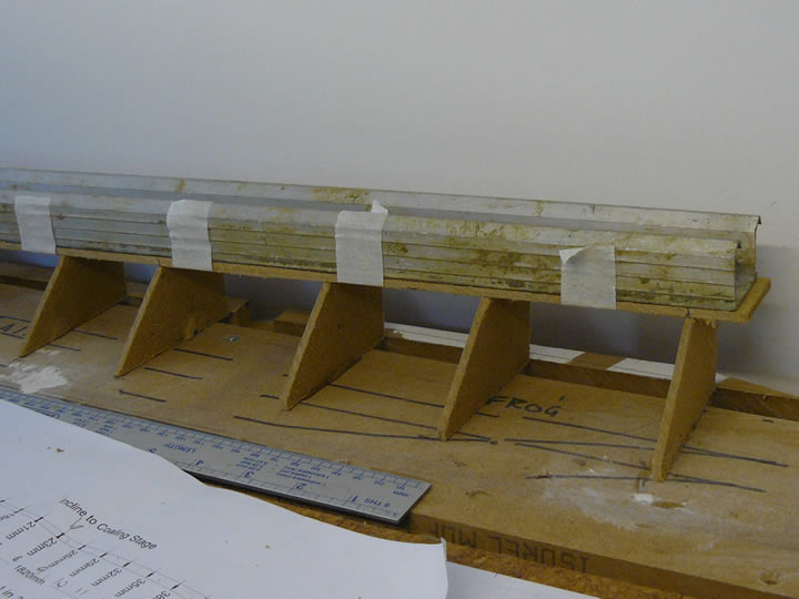 Formers were cut from hardboard, using the height dimensions calculated during the planning process; a print showing this is visible in the picture. The edge of the formers was cut to a slope of 45° and the top to the width of the track bed.
 The outer formers for the 1 in 35 approach were fixed in place with a hot glue gun. A strip of hardboard the width of the track bed was taped to the bottom of a length of aluminium angle to keep it rigid, and then placed on and glued to the outer formers. The intermediate formers could then be glued in position and to the underside of the track bed as can be seen in the photograph. |
|
| Building the incline - 2 |
| |
 Once all formers and the track bed were glued in position, the tape and the aluminium angle could be removed. The resulting structure is remarkably strong.
A suitable gap was left to accommodate the coaling stage itself, and the process was repeated for the 1 in 100 incline. The overhanging lengths of hardboard will be trimmed off before the coaling stage is built. Although the structure is strong, we decided to add bracing, fabricated from off-cuts of hardboard - the first pieces are visible in the photograph. Although the incline will not need to support great weight, it is better to be safe than sorry! |
|
| Building the incline - 3 |
| |
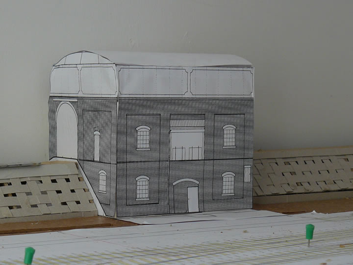 Peter fabricated a mock-up of the coaling stage out of thin card; the fascia was scanned from a drawing of the structure scaled up to the correct size. This gives a good impression of what the final structure will look like.
The incline was then covered with interwoven strips of card, bonded with a hot glue gun, using the mock-up to ensure the incline correctly mated with the structure. Sufficient allowance has been made for sleeper height and further covering of the incline to bring the finished structure to the correct size and profile. |
|
| Building the incline - 4 |
| |
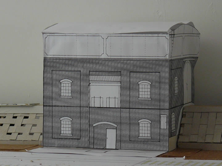 The weaving technique is quite clear in this picture; The vertical section at the bottom will be a retaining wall.
 Also visible are further track templates that are being carefully positioned to retain the precise alignments afforded by Templot. The scanned image on the mock-up shows the outline of the water tank that was a prominent feature of these distinctive Great Western structures. To our surprise, the pattern on the tank sides is simply decorative paint and not, as imagined, a structural feature. This became clear from photographs taken at Didcot (see below) and subsequent examination of photographs of similar structures in various books. |
|
| Site Visit |
| |
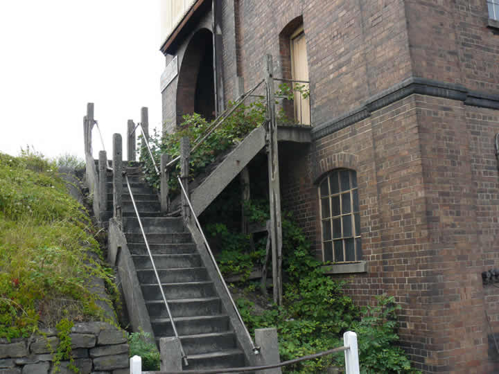 One of the crucial elements in the pursuit of authenticity is a visit to the prototype. Depending on the period and area being modelled this can be difficult, if not impossible. However, we are fortunate in that examples of Great Western running sheds are still extant, and one of the finest is the Great Western Society site at Didcot, in Oxfordshire - fortuitously also the shed on which the drawings used in our planning and design work was based.
So, for one of our weekly model railway sessions, we visited Didcot and took hundreds of photographs of the shed and the coaling stage, both inside and out. Unfortunately the turntable now at Didcot is not a GW pattern one and so was of little help As luck would have it, we were inside the coaling stage when a Pannier drew up alongside and we were able to see the workings of the tubs used to coal engines. Replicating those will be an interesting modelling challenge! The picture shows the rather overgrown access stairs leading to the coaling stage; it shows some of the important details such as the decoration on the English bond brickwork. We were intrigued by the intricate stairway, in particular the need for the extra steps to the access door which opens into the interior which is also reached by the continuation of the steps to the ramp level above. The undergrowth will not be replicated on the model, as I have not seen this in any photographs of working sheds in the days of steam. |
|
| A Question of Scale |
| |
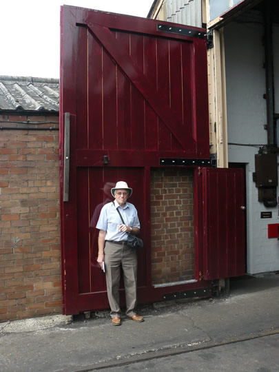 This photograph was posed so that we have an easy way of scaling the woodwork on the massive shed doors. This is Peter Howell, Grindham's master builder; you can see examples of Peter's models by visiting our previous layout Grindham
The brickwork in this picture is a good illustration of the importance of a site visit to record detail. The brickwork at the left is stretcher bond - and probably, therefore, a later addition; that visible through the open doorway is English bond. I am not sure that the doors would be in such fine condition during the 1950's, but they are a testament to the dedication of the members of the Great Western Society and an indication of the massive job they have in keeping the infrastructure in good order - not, perhaps, so "glamorous" as restoring steam locomotives, but vital, nevertheless, in preserving our railway heritage. Even if you are not planning a model, a visit to Didcot is thoroughly recommended. There is an impressive stud of locomotives and rolling stock and it is a great day out and a way to help support the Didcot Railway Centre and the Great Western Society. |
|
| The Shed - Taking Shape |
| |
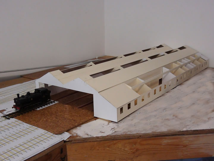 Following our visit to Didcot, and armed with countless photographs to supplement the scale drawings, Peter felt confident enough with the information available to make a start on the shed building.
 You can see the basic shell in the photograph, and already the characteristic shape of a Great Western shed is apparent. The building is big - 840mm long! I have stationed a Pannier tank at the entrance to give a sense of scale and you can also see the inspection pits, described in the Baseboards chapter. Although these will be largely hidden once the structure is complete and stocked with locomotives, their presence is, nevertheless, important in capturing the character of a shed. The basic structure uses card; when glued with suitable bracing it makes a very strong shell. |
|
| First bricks laid |
| |
 The brickwork for the shed offices was created by photographing an English bond brick wall, and using Photoshop to get it to the correct scale and create large panels for use on the model. This has the great advantage of replicating the random shades found in bricks, which is both difficult and tedious to reproduce with paint. It also allows Peter to combine this with his other hobby of photo-editing.
The area in front of the shed has been covered with hardboard and is a site for future development. Current thinking is a row of terraced houses backing onto the shed boundary. |
|
| Shed Offices |
| |
 The pleasingly authentic "random" brick pattern generated from a photograph is illustrated here. The potential for computers to assist our hobby seems endless - they really are a great asset.
The roof tiles on the office block have also been generated in a similar fashion; the resulting print is cut into strips that are overlaid to replicate the overlapping rows of tiles, which ensures that rain water runs down the roof to the gutter. |
|
| Shed windows |
| |
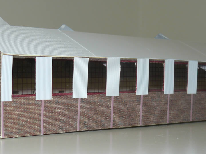 The other side of the shed features large windows - presumably to allow light inside, though in use they would, no doubt, soon get very grimy. These have also been created on a computer, by printing the bars onto OHP slide transparencies.
 The vertical stripes are the girders of the steel framework of the shed structure; the upper part of the walls and much of the roof are clad with corrugated asbestos. The original building on which this model is based was erected during the 1930s as part of the Government loan scheme, intended to help the country out of the great depression by creating jobs; the Great Western Railway was one of the companies that took advantage of the scheme to improve its infrastructure. |
|
| Shed rear |
| |
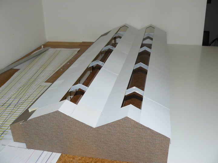 This shot shows the rear of the shed; this will actually be hidden when the shed is in situ on the layout
Working on this model is very difficult due to its size (840mm by 310mm) which makes it very unwieldy. The problem will get worse as details are added, especially the clerestory roof with walkways and handrails! |
|
| Coaling Stage - First Fitting |
| |
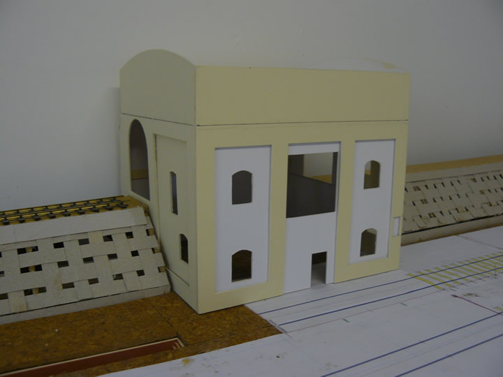 The shell of the coaling stage has been positioned to check for fit, before proceding with further construction. It has been designed so that the outer "shell" and the inset panels can be separated to enable the brickwork to be added more easily.
 |
|
| The next stage |
| |
| With the main structure substantially complete, Peter will be concentrating on adding the host of details to the shed building. |
|