|
|

|
| Chapter
3: Track |
| |
| In this chapter I will endeavour to explain the process of track construction. One of the great benefits of P4 (or any other exact scale) is that the track looks like the prototype, whereas manufacturing constraints make this virtually impossible for mass produced ready to run track. This is especially evident where switch and crossing work is involved, as should become more evident as the work progresses. The down side, of course, is that building track takes time and patience. It is also, I think, something that frightens a lot of people away, so I will try to show that it is not that difficult, and that the end result justifies the effort required. |
| |
| First Stage |
| |
 The fitting of the final track templates in position marks the beginning the chapter on track construction. With the templates all aligned and secured, the shed area is beginning to take shape and the layout of the track is now defined.
Work can start on construction of the 16 turnouts and laying the plain track as defined by the plan. I will start by constructing one of the turnouts in the approaches to the shed roads; track and further turnouts can then be built from this datum Construction will proceed at a leisurely pace, with frequent checks for reliable operation. There will also be some experimentation with techniques, for example in fixing the unsleepered rails either side of the pits and in the paved areas. Unfortunately, my preferred components, as described below, are no longer manufactured so further investigation into alternative methods may also be necessary. |
|
| Timber Preparation |
| |
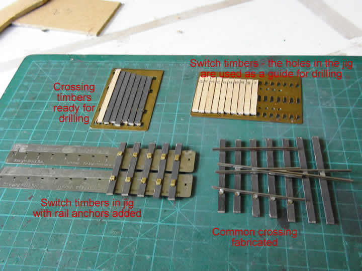 Initially, I am using some Exactoscale components that feature scale thickness wooden timbering and brass anchors to which the rails are fixed. It is a beautifully simple system - alas no longer manufactured, but I will persist until my stock of components runs out.
This system utilises jigs both to drill the timbers for the rail anchors and then to hold the anchors in place, with the timbering correctly spaced. The two jigs at the top of the illustration show the timbers held in position for drilling - you can see the holes that are used as a guide for the drill. The bottom left hand jig is partially loaded with switch timbers with the brass rail anchors inserted. The switch and the common crossing are built as units, which are then incorporated to make the turnout. At bottom right is a common crossing with the rails soldered onto the anchors The system is very flexible with jigs and anchors available for various switch lengths and crossing angles; because of the soldered construction, the end result is also very strong. I will provide further details as construction progresses. |
|
| Turnout Construction |
| |
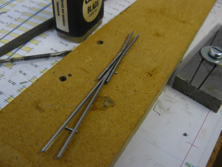
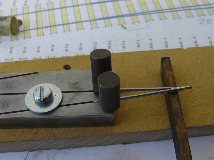 The first stage in constructing a turnout is to fabricate the common crossing - referred to as "the frog" by some modellers. Here you can see the "vee" being made. This is built from two lengths of rail, filed so that when soldered together they form a "vee" of the required angle - in this case 1:8, as this is for a C8 turnout.
I use a jig both to file the rails to the correct shape and then to hold them together at the correct angle for soldering as can be seen in the photograph. This jig can be used to fabricate the four angles from 1:5 to 1:8; I have another for 1:9 to 1:12. I bought mine from the Scalefour Society Stores, but they are manufactured by Portsdown Models The rail sections are held in place by rare earth magnets - exceptionally strong - and the nose of the "vee" is supported on a piece of timber to ensure it is flat when soldered. The jig can also be used to set the correct angle for the wing rails - the other vital components of the common crossing (see below). |
|
| Crossing Assembly Jig |
| |
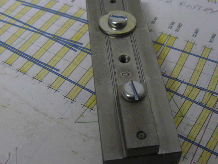
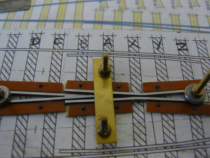 As the layout will have 16 turnouts - all of which have to be hand built - I decided to make a jig to help with fabrication of the crossings, which can be seen in the accompanying photograph.
I used my trusty Templot software to print out a 1:8 crossing and fixed this to a piece of MDF. I carefully pinned lengths of copper clad PCB strip (copper side down), using the template for positioning, so that they would support the "vee" and the wing rails in the correct position as shown; as the PCB is slightly thinner than P4 rail height, the rail stands proud and 8BA nuts and bolts, washers and a strip of brass can be used to clamp the rails firmly in position against the PCB supports. The nose of the "vee" rests on timber "A" and is held in place with the brass strip. The rail sections are inserted upside down to enable subsequent soldering on the underside as described in the next section. In forming the "vee" and bending the wing rails it is vital to ensure the track is not bent vertically and will sit flat in the jig. The picture shows the jig in its prototype state; I can reduce the length of the fixing bolts for future use. As my off-cut of MDF was rather narrow, I had to trim the useful Templot annotations from the template - hence my scribbled timber designations! Most of the turnouts are 1:8, but it will be easy to fabricate a similar jig for different angles. |
|
| Crossing Fabrication 1 |
| |
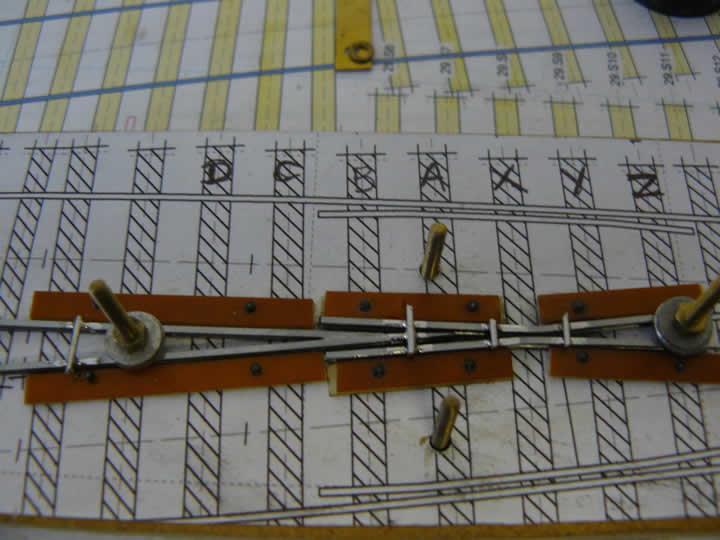 Before removing the brass clamp, I soldered lengths of brass wire to the underside of the rail sections; two wires are used to join the wing rails (either side of "X" timber) and a third to maintain the correct alignment of the "vee" (at left of the picture). Using the timber outlines on the template as a guide, I made sure the wires were soldered between the timbers where they will not be seen once the excess wire has been trimmed and the unit installed and ballasted. Thin brass strip (from the edge of frets) could be used instead of wire. Like any soldered joint, cleanliness of both surfaces is paramount; Carr's "Black Label" flux is my preference for soldering steel.
Once these were soldered, the centre clamp was removed to fit the final wire (between "B" and "A" timbers) to fix the nose of the "vee" to the wing rails either side. This is an important join to ensure the nose does not move under load. |
|
| Crossing Fabrication 2 |
| |
 The bonding will give the unit strength - important as the remainder of the turnout will be based on this component - and should maintain the clearances required to steer wheels through the point. The flangeways were carefully checked with a gauge (also from Scalefour Stores) to ensure correct clearances and alignment, essential for reliable running. It will now, of course, be electrically continuous, which will also aid running.
The unit was carefully washed and dried off once completed - the Black Label flux is highly corrosive. Further careful cleaning will be necessary as construction proceeds and check and stock rails are added. Although it is very difficult to prevent corrosion, especially where there is so little clearance and access for cleaning is thereby restricted, I much prefer steel rail to nickel silver; steel, after all, looks much more like steel! |
|
| Crossing Fabrication 3 |
| |
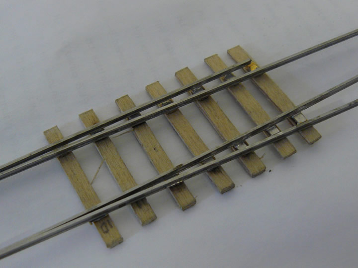
 A landmark - the first section of track laid!
The common crossing has been fixed to the timbers using the Exactotrack anchors described earlier, and the check and stock rails fitted. The crossing is still far from complete, as the chairs have to be added, but I will assemble the whole turnout and add the approach and exit tracks to make sure it works before adding the cosmetic refinements. Before this panel is finally fixed in position, dropper wires will be attached to the underside of the common crossing and the stock rails in preparation for the wiring. Forward planning is always a good idea, and fixing them underneath means they are invisible once the track is laid and ballasted. Despite the whole unit having been thoroughly scrubbed with detergent and then rinsed and dried, there is already slight corrosion appearing - the photograph was taken only a few hours afterwards - illustrating the problems of soldering steel rail using corrosive flux. The corrosion is slight and will easily clean off. |
|
| Switch Fabrication - 1 |
| |
 With the crossing built it is time to tackle the other part of the turnout - the switch. This is also a critical component as it includes the moving switch rails and these have to be planed to the correct shape to enable wheels to be directed smoothly in the required direction.
To reproduce the prototype as accurately as possible, the planing is a bit complex as the foot of the rail needs to be left intact on the side of the switch that faces inwards - i.e. that is not in contact with the stock rail when the switch is closed. The planing also needs to be correct for the size of switch - in this case a "C". Happily there is the very useful jig illustrated in this picture, which is also available from the same source as the crossing jig described above. This jig will make pairs of switch rails for the four sizes from "A" to "D"; the rail is clamped in the slot, with a block covering the foot as can be seen in the photograph. The surface of the jig is angled for the appropriate length for the switch size, and the rail is simply filed until it is flush with it, with the block preserving the foot. Then, having first removed any burrs, the two rails are replaced in the jig with the other side up and, without the block, filed smooth to the surface of the jig. The jig is so simple and effective - what genius! Both this and the crossing filing jig described earlier were the brainchildren of Peter George. |
|
| Switch Fabrication - 2 |
| |
 The switch and stock rails have been soldered to the anchors to form the switch unit. As with the crossing, the anchors give the switch unit strength and maintain the correct gauge.
 I now need to get some GW 2-bolt chairs so that these can be added to the switch and stock rails before the slide chairs and stretchers are fitted. The timbers also require a coat of paint or staining to replicate the prototype's stained and weathered appearance. |
|
| Shed Roads - 1 |
| |
 The problem of fixing the track either side of the inspection pits received a lot of thought. Several ideas were considered, but in the end I decided to solder the rail to the edge of a brass strip, which can be drilled and screwed into place as in the accompanying picture. This should keep the rail straight and prevent movement, and the brass strip will be hidden under card painted to represent the oily surface of the shed floor.
 |
|
| Shed Roads - 2 |
| |
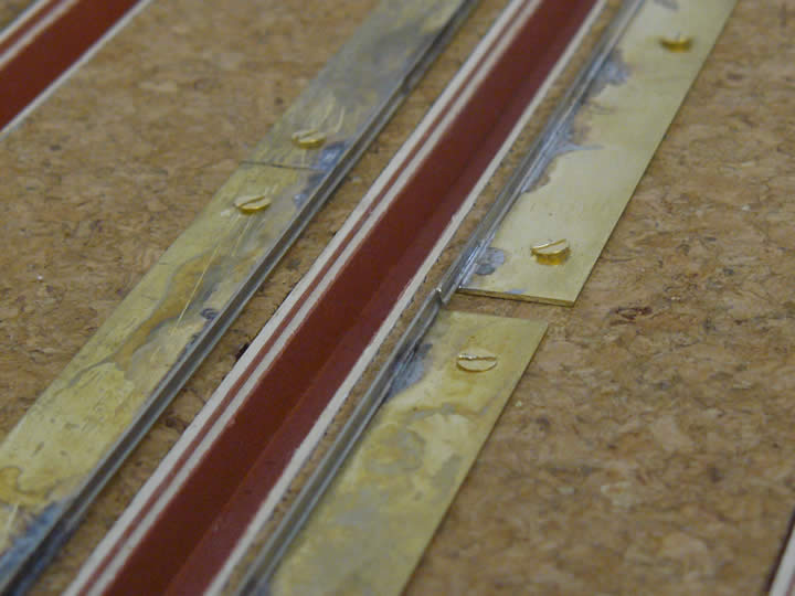 Electrically, one rail of all the track will be the common return, so one side here is a continuous length of rail, soldered to lengths of brass. This then provides a datum to gauge the other side, which is made up of "Pannier" length rails, electrically isolated from one another; this should be clear in the photograph. These isolating sections will be wired to switches on the control panel.
 |
|
| Shed Roads - 3 |
| |
 Each isolating section will accommodate a Pannier tank; larger engines will require two sections. Here you can see a "Grange" Class 4-6-0 occupying two sections, with a pannier a third.
The "metre stick" seen in the photograph is an essential tool to get the continuous datum rail straight. The brass strips used to fix the rails in place will also make a useful terminal for the electrical connections Once all the rails and wiring are in place, we will be able to add the special chairs used to fix rails in these situations. |
|
| The Next Stage |
| |
| Now the technique for fixing rails either side of a pit has been decided, work on building the approach tracks can be continued. |
|
|
|
 |
|