|
|

|
| Chapter
2: Baseboards |
| |
| Stable and flat baseboards are essential for a successful model railway. The boards not only underpin the tracks, but also provide support for the various "services" - notably wiring and point operating mechanisms - hence the need for a strong and stable platform. However carefully you lay track, it will inevitably perform poorly if the baseboards are not right. |
| |
| Introduction |
| |
 The baseboards featured in this chapter were recovered when we dismantled our previous layout Grindham. Originally built to fit in my model railway room, they were subsequently adapted and extended to accommodate the monster that Grindham became - 32ft long! Now, with the fiddle yards dispensed with and reverting to original configuration, four of them will again fit (just) within the confines of my den.
Here you can see the framing, partially covered with MDF which is an ideal surface as it is flat, tough and, when kept dry, does not warp. The disadvantage is its weight, an important consideration for an exhibition layout, and so the boards were built as open topped frames, which allowed MDF to be used under the track only, leaving the scenery to be placed on lighter materials. Only one board has legs at both ends - the others "piggy back" on this, thus reducing the number of legs required and making for easier transportation and erection at exhibitions. Scarring from previous use is very evident, as is the tendency for boards to become a repository for accumulated junk when they are not being worked on! |
|
| Open top framing |
| |
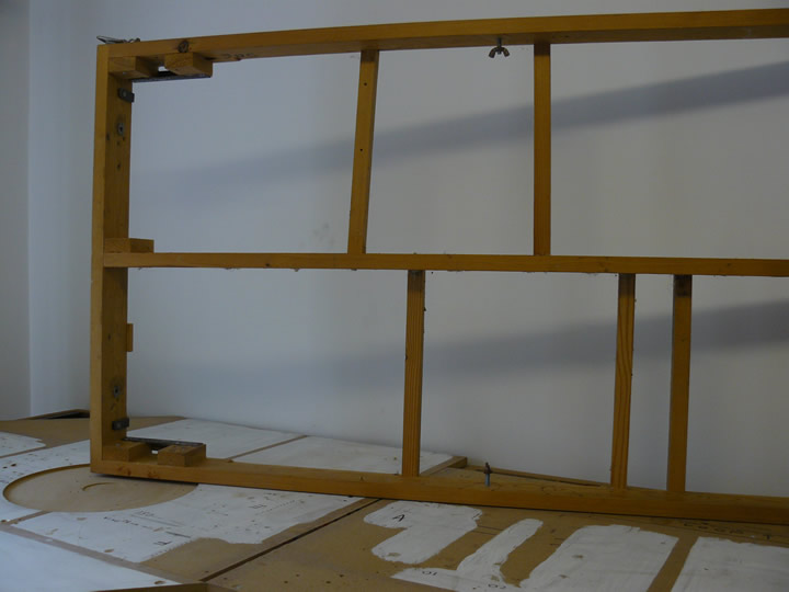 This illustrates the construction of the open top boards employed. All the strength is in the outer framing and the longitudinal member - the thin cross members can be positioned anywhere to provide supports.
The legs, formed in an "H" shape simply slot into the framing between the wood blocks at the left hand end, and diagonal braces are secured with butterfly nuts to the framing. This enabled the legs to be detached easily for transport whilst providing the stability needed. This board will eventually be used for the purely scenic section mentioned in Chapter 1 - Planning and Design; serious re-organisation of the model room will be required to accommodate it! |
|
| Finger Alignment |
| |
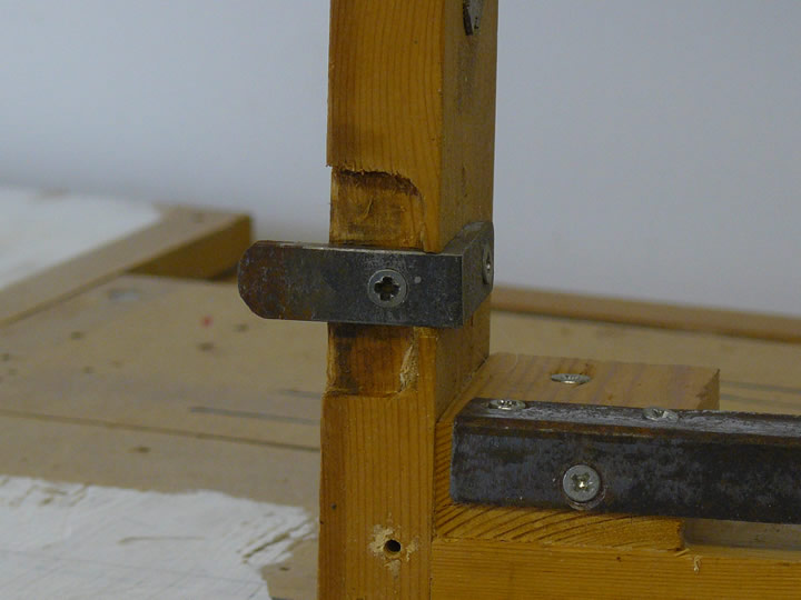 Although I had hacked lumps of wood into reasonably successful baseboards previously, I am no carpenter and so I had these built many years ago. Jim Walpole, who made them, used this ingenious device to align the boards accurately - essential as the layout was being built for exhibitions. The "finger", cut from a piece of steel angle, fits tightly between two similar pieces attached to the adjacent board and which sit in the recess that can be seen in this illustration.
The picture also shows the steel angle used as a cap across the slot into which a leg fits |
|
| Fingers Aligned |
| |
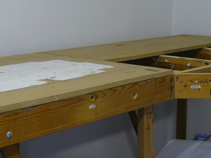
 A picture is worth a thousand words, and this illustrates admirably how the fingers align the boards. As the fingers are recessed and flush with the top of the framing, they can be covered over, as on the right hand board in this illustration - the left hand covering has been moved to reveal the fingers for this example. They are thus invisible once the boards are joined together and track or scenery built over their location.
Once the boards are aligned with the fingers, a couple of long bolts and butterfly nuts secures the board ends together. So simple, but very effective, this ensures perfect alignment every time. |
|
| Shed Area |
| |
 This is the site of the shed building. It will, like the prototype, incorporate inspection pits between the rails and therefore we have not covered this area with MDF. Instead, we will install longitudinal supports spaced the correct width for the pits to which the rails will be attached. Similar pits will also be constructed in the Ash Road on the approach to the Coaling Stage.
The bolt to the left of the picture secures the angle brace to the leg. The piece of MDF that will support the shed approach tracks was recovered from "Grindham"; this white area was then on the underside and painted so that labels denoting the various electrical connections under the layout were more easily visible. Evident in this shot is the substantial timber employed in the framing; in retrospect, this would have been better done using plywood, which would have been a lot lighter; as we do not intend to take the new layout to exhibitions this is not an issue. |
|
| Turntable Area |
| |
 The need for careful planning is nowhere more important than for the turntable area. This has to be accessible both during construction and in operation; it also requires unobstructed space below, to accommodate the operating mechanism. Because we are re-using old boards, we will have to modify the framing accordingly, but at least we know this before serious construction has commenced.
Accurate alignment with the track plan is essential, and so witness lines were carefully drawn from the Templot plan before the board was removed to have the well excavated with a router. Great care will be required to re-align with the plan. |
|
| Turntable Well |
| |
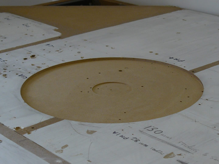 Great Western over girder turntables had quite shallow wells, and so this one has been routed out of the MDF to the correct depth and diameter.
The inner well on the prototype houses the pivot. This has not been routed too deep to ensure that the centre is preserved for fitting the operating mechanism. It will, in any case, be virtually invisible under the turntable bridge so excavation to the full depth is not necessary. The various holes visible in the MDF accommodated wiring in its previous life, and will have to be filled in. This piece of MDF has also been inverted, and the dimensions for the well are visible on the white painted surface, along with some of the old wiring annotations; I cannot remember what "CIA" denoted, but it had nothing to do with the eponymous American institution! |
|
| Deep excavation |
| |
 As noted earlier, the old boards needed some reworking to accommodate the turntable mechanism. Fortunately, they were so robustly engineered that removal of one of the cross members would make no appreciable difference to the stability, and once the MDF has been screwed in place on top any compromise to the rigidity will be remedied anyway. Here you can see the "excavation"; removal of this cross member will give more than adequate space for installation of the turntable operating mechanism.
After this picture was taken, the turntable board was fixed in position, and the spurious holes from previous use filled in. |
|
| Surface preparation |
| |
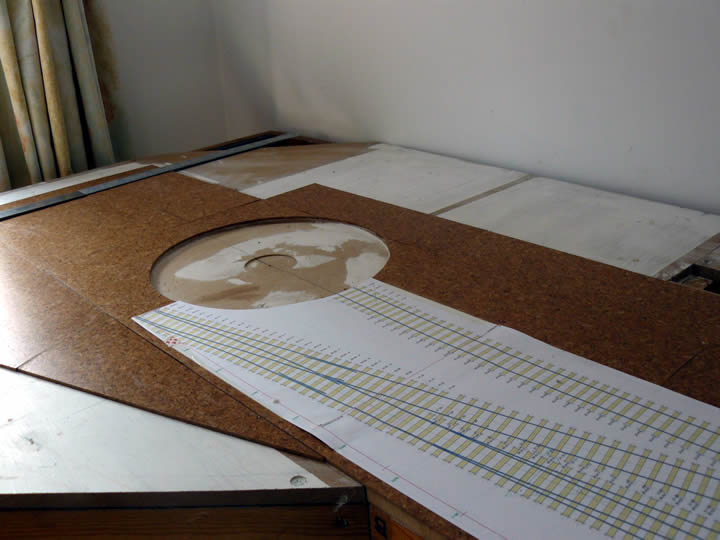 All areas under trackwork will be covered with cork. This has several advantages. First and foremost, it is flat and a flat, even surface is a prerequisite for smooth and reliable running. It also provides good sound insulation; otherwise, there is a tendency for the sound of trains on rails to resonate with the baseboards acting as amplifiers. Being relatively soft, cork accepts pins very easily - ideal for temporarily fixing track panels in position. Finally, it is also relatively cheap - the cork tiles used here were from my local Wickes store and cost just over £15; there will be more than enough for this layout. The cork tiles are fixed down with PVA adhesive.
The area in the picture is the turntable and we have started to lay the Templot templates; the line onto the turntable bridge is critical, and so this has been used as the datum for placing all the subsequent templates. |
|
| Excavation of ash pit |
| |
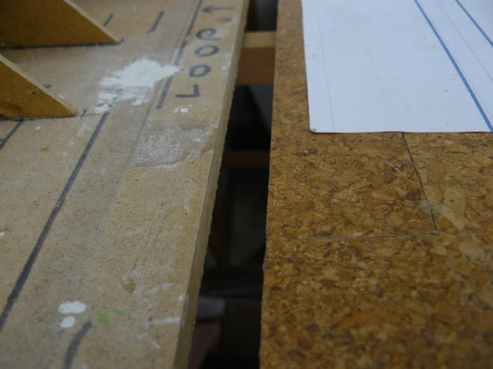
 With some of the track templates in place, the position of the ash pit can be set precisely and a corresponding hole made in the baseboards. This is being achieved by placing a strip of MDF to delineate one side of the pit, as seen in this picture; a strip of MDF can then be cut to form the other side. The pits themselves will be constructed as card troughs, to be installed between the MDF supports.
The notch in the piece of MDF is from its previous incarnation as part of the old Grindham layout; the notch would, of course, be on the straight edge as decreed by the Universal Law of Sod, and so will have to be filled in. The line without sleepers seen on the template is part of the ash removal road that runs parallel to the pit; the area will be paved - hence there will be no sleepers. |
|
| Track templates |
| |
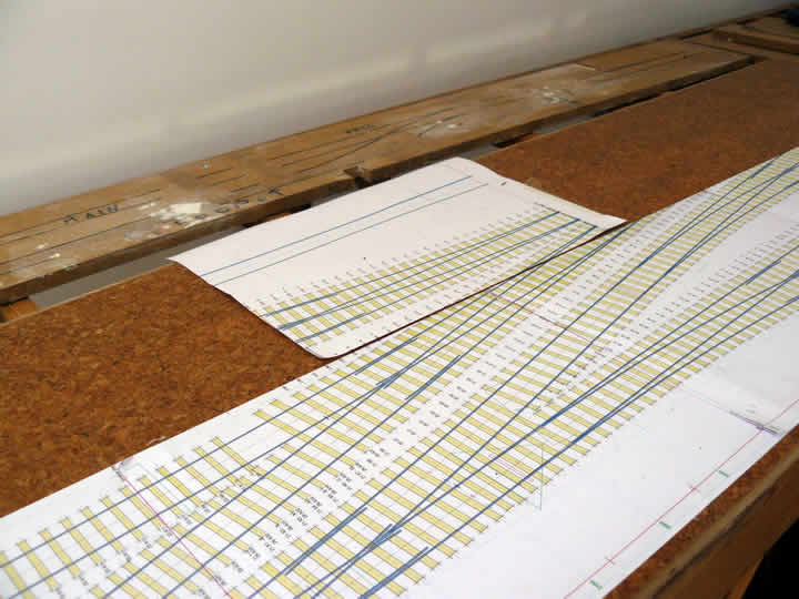
 Laying cork and fitting templates proceeds in parallel; this allows us to use the templates to establish the exact position of critical structures like the ash pit and the coaling stage.
I have included this picture to illustrate some of the details incorporated in the Templot templates - the actual rails, including the components of point & crossing work, the sleepers, each individually numbered, as well as many other useful pieces of information such as the position of the tie bar, track centre lines, rail joins, and so on. The Planning and Design section gives more details about using Templot, or visit the Templot website. If only building the track were as simple as printing the templates! All Templot illustrations are ©85A Models and are reproduced by kind permission of Martin Wynne. |
|
| Ash Pit |
| |
 The ash pit is finally taking shape, and the cork covering has been extended to one of its edges. With the formers for the incline installed (see under "Structures & Scenery"), the remainder of the cork can be laid in this area ready for the remaining templates to be placed in position.
The unsightly "notch" has also been filled in, although this is not visible in the photograph. |
|
| Inspection Pits - 1 |
| |
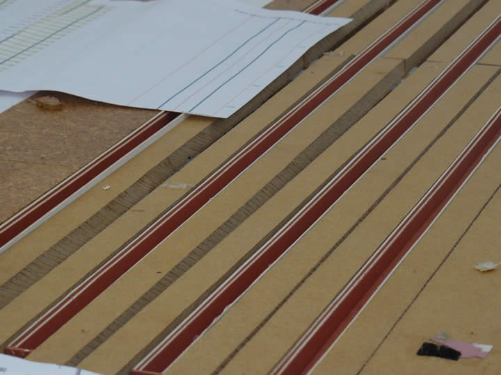
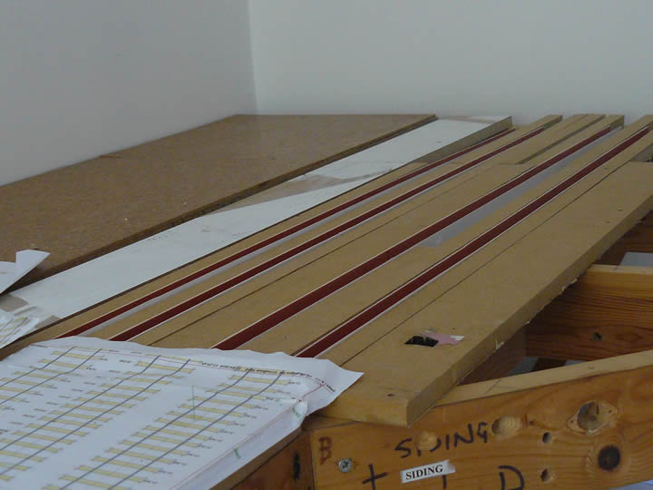 The slots in the baseboard under the loco shed can be seen under construction; they will form the inspection pits located under the tracks.
 These are being fabricated in the correct dimensions from card; strips of MDF are then being inserted to provide strength and a foundation for the rails. The pits will be carefully aligned with the track templates once these have been fixed in the correct position. |
|
| Inspection Pits - 2 |
| |
 During a visit to Didcot, we took many photographs, including details of the inspection pits. This has allowed construction to proceed with more confidence!
This picture shows the "stepped" sides to the pits, which Peter has replicated in card. Although these will be largely hidden once the shed is built, it is important to be as accurate as possible. The strips of MDF will support the rails and lend strength; they will subsequently be covered to represent the concrete floor inside the shed. |
|
| Inspection Pits - 3 |
| |
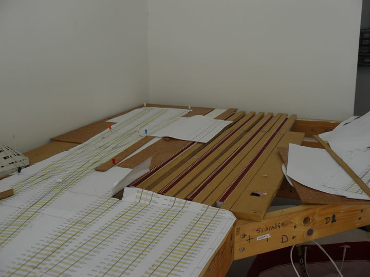 Careful alignment of the pit roads with the pits themselves is very important; the pits must also be kept parallel and the correct distance apart within the shed itself.
This view shows the pit road supports being installed, using the Templot templates as a guide. The coloured pins are holding the templates for the track from the Coaling Stage in place, prior to fixing down. |
|
| Next Step |
| |
| Once the supports for the shed roads are fully installed, work on the baseboards is pretty well complete for the time being. Further work will be required on the scenic board, but that is some way in the future. At a much later stage, we may add a valence around the board edges to make it look neater. |
|
|
|
 |
|